Wednesday, March 25, 2009

Car air conditioning system operation

Air Conditioning

Air conditioning is a system used to create and maintain a comfortable driving environment inside a vehicle. It does this by transferring the heat from inside a vehicle to the outside keeping the temperature down inside the car.The system cools, dries and cleans the air.

The most basic systems have manual temperature control but systems are becoming more and more complex with full climate control on a lot of modern cars which rely on a lot of sensors to maintain the selected temperature.

Air conditioning system schematic diagram-basic system

Air Conditionaing

Common Air conditioning problems

Air conditioning system not cold enough

The Air Conditioning system in your vehicle is not usually covered by most manufacturers servicing schedules and the refrigerant gas that is used to operate the system depletes over time. On average most vehicles lose up to 15% per annum this problem can be caused when then system is not used during the winter months allowing the small “O” ring seals to dry out resulting in a gradual deterioration in system performance eventually resulting in the system being too low to operate at all.

Most problems of this type can be put right fairly easily by a leak check of your system followed by a complete refill of your air conditioning refrigerant, this is sometimes referred to as a re-gas. Please contact usfor your air con annual service or re-gas if you live in the Cardiff,Swansea, Bridgend or Newport area.

Air conditioning system smells odd

If you notice any strange smells when you put your air-con on then this could be signs of bacteria build up on your system.

As systems become older or are used infrequently the air conditioning system can start to develop bacteria, micro organisms and even mould or fungi growing especially behind the dash panel on the evaporator, this can lead to some very unpleasant odours. Some even claim this can result in headaches and flu like symptom sometimes referred to as sick car syndrome.

Don’t suffer any longer air con systems can be treated effectively with an anti-bacterial treatment that destroys the bacteria growth and leaves your car smelling fresh again.

The earlier this is treated the better you will feel!

Please call for a quote. from one of our mobile air con repair technicians.

If your air-con system suddenly starts making noises you have not heard before it is very advisable to have a qualified vehicle air conditioning specialist to have a look at it.

Some noises could be early symptoms of a compressor failure (the compressor is the air conditioning pump).The compressor is usually the most expensive part on the system ranging from approximately £230 to £600+ and if the bearings in your compressor break down or if the compressor seizes up it also means that other components can become contaminated with metal particles A flush of the system would then be needed as well as replacement of the compressor, the receiver / drier and the expansion valve - quite a hefty repair bill!
Its not all bad news however - some noises are quite normal

There are 2 different types of air-con system operation some vehicles use a system where the compressor (pump) cycles on and off which means that there is a clicking noise heard every few seconds this is normal, however if this switching cycle changes noticeably or the air con is not very efficient this could be an early symptom of low refrigerant or low gas pressure.
Pool of water underneath the car after using air-conditioning
You will sometimes see a water puddle on the ground, usually under the passenger footwell area, this is a normal feature of the air conditioning system as it is only water dripping from the air conditioning evaporator which has a drain tube fitted to allow the condensation from the evaporator to drain away from the vehicle.
Damp carpet in the footwell or excessive misting of the windscreen

Sometimes the drain tube from the evaporator may become blocked or detached allowing the condensation to build up inside your evaporator if this occurs water will just build up inside your car to a point where there are damp carpets or misting / high humidity type problems.

Tuesday, March 24, 2009

Electrical Charging System Basics

Charging System Basics:
The electrical system in an automobile is said to be a 12 volt system, but this is slightly misleading. The charging system in most cars will generally produce a voltage between 13.5 and 14.4 volts while the engine is running. It has to generate more voltage than the battery's rated voltage to overcome the internal resistance of the battery. This may seem strange, but the current needed to recharge the battery would not flow at all if the charging system's output voltage was the same as the battery voltage. A greater difference of potential (voltage) between the battery's voltage and the alternator's output voltage will provide a faster charging rate.
As long as the engine is running, all of the power for the accessories is delivered by the alternator. The battery is actually a load on the charging system. The only time that the battery would supply power with the engine running is when the current capacity of the alternator is exceeded or when engine is at a very low idle.

Alternator Basics

Overview:
A basic alternator has 2 main electrical components. The rotor and the stator. The rotor is the part of the alternator that is spun by the drive belt. There are a group of electrical field coils mounted on the rotor. The stator is the group of stationary coils that line the perimeter of the inside of the alternator case. When current (supplied by the voltage regulator - to be explained later) is flowing in the rotor's coils, they induce current flow in the stationary coils. The induced current (and voltage) is an AC current. To convert this to DC, the current is passed through a bridge rectifier.

Stator and Rotor in Action:
In the following diagram, you can see three crudely drawn sets of rotors and stators. In the leftmost diagram (marked 'A'), you can see the rotor's coil approaching the stator coil. As the rotor coil approaches the stator coil, it induces current flow in the stator coils. This causes an increase in output voltage. As it approaches the position where the coils' centers are aligned ('B'), there is no induced current. When the coils move away from each other ('C') the induced current flows in the opposite direction and the generated voltage is negative.


Rectification:
You should have noticed that the generated voltage was AC. You already know that a vehicle's charging system needs to produce DC to recharge the battery. This is done with diodes. The following diagram shows a simple transformer and a bridge rectifier. The transformer is driven with a sine wave (similar to that produced in each stator coil). Since the transformer is driven with a sine wave, the output of the transformer is a sine wave (similar to the one shown). The sine wave is driven into the bridge rectifier and the output is a pulsed DC waveform.

Bridge rectifier:
You should also realize that there are 3 different groups of stator coils in an alternator (not shown in diagrams). The rectification is much like the simple transformer shown above but in the place of a single transformer winding there are 3 windings. It also uses 6 diodes instead of 4.

3 Phase:
The following diagram shows the 3 different phases from the 3 groups of stator windings. The three phases of AC are shown in three different colors. The next set of lines shows the rectified waveforms overlapped. The bottom waveform (white line) is what the rectified voltage would actually look like if viewed on an oscilloscope. Connecting the battery to the alternator will smooth the white line even more.

Alternator Schematic:
The following is a generic schematic showing the stator windings and the bridge rectifier. You also see a diode trio. the diode trio takes part of the output and sends it to the voltage regulator. The output diodes are the rectifiers that rectify the AC and supply power to your electrical accessories.

Brushes and Slip Rings:
For an alternator to produce electrical current, there needs to be some excitation current flowing in the rotor windings. Since the rotor is spinning, you can't just connect a couple of wires to it (cause they'd just be twisted off :-). To make the electrical connection, slip rings and brushes are used. The slip rings are fixed to the shaft of the rotor. The brushes are fixed to the stationary part of the alternator. The brushes, which are generally made of carbon, are spring loaded to keep constant pressure on the slip rings as the brushes wear down. The following diagram shows the general location of the rotor and the associated parts.

Voltage Reguation:
As you already know from the 'wire' page, all wire has resistance. You also know that when you have current flow through a resistive element (wire), there will be a voltage loss. If the current draw from the charging system was constant, there would be no need for a voltage regulator. If there was no loss, the design engineer would simply design the alternator to produce a given voltage. This won't work with a car audio system because the current draw is anything but constant. This means that the alternator needs a compensating voltage regulator. The voltage regulator controls the flow of current in the rotor's windings. The voltage regulator's output current will typically be between 0 amps (with little or no current draw) and 5 amps (at maximum current draw). The regulator can vary the current flow infinitely to keep the voltage precisely at the target voltage. Generally the regulator is built into the alternator. There are some high current/special use alternators which may have external regulators. Some of the external regulators are adjustable via a potentiometer.

Current demand and flow:
If you have an alternator that can produce 120 amps of current (max) and the the total current demand from the electrical accessories (including the battery) is only 20 amps, the alternator will only produce the necessary current (20 amps) to maintain the target voltage (which is determined by the alternator's internal voltage regulator). Remember that the alternator monitors the electrical system's voltage. If the voltage starts to fall below the target voltage (approximately 13.8 volts depending on the alternator's design), the alternator produces more current to keep the voltage up. When the demand for current is low, the full current capacity of the alternator is not used/produced (a 120 amp alternator does not continuously produce 120 amps unless there is a sufficient current draw).

Dimming lights:
When you play your system at very high volumes and the lights on your vehicle dim slightly, it generally means that your alternator can not supply enough current for all of your electrical accessories (including your amplifiers). If you play a long bass note/tone and the lights get dim and stay dim until the note is over, your alternator clearly can not keep up with the current demand. If, on a long bass note, the lights dim just for a fraction of a second but return to their original brightness while the note/tone is still playing, the alternator's regulator may just be a little slow in reacting to the voltage drop. Since the lights return to their original brightness during the bass note, the alternator is able to supply the current needed by your power your amplifiers and other electrical accessories.

Warning!

Some people tell you that you can check your alternator by disconnecting it from the battery to see if the alternator can produce enough current to keep the engine running. BAD IDEA!Disconnecting the battery will subject the voltage regulator (and computer and audio equipment...) to significant voltage spikes which may cause an otherwise good alternator to fail. Even if there were no damaging spikes, this test would not indicate whether or not the alternator was good because the engine will easily run with a weak or failing alternator.

Simple Test:
If you want to see if your alternator is producing current, turn on your headlights when you're parked and the engine idling with the headlights shining on a wall (at night). Notice how bright they are. Then turn the engine off. The lights should get dimmer when you turn the engine off. If the lights get brighter when you kill the engine, the alternator was not charging sufficiently. When doing this test, the lights should be the only load (turn the stereo, a/c and other accessories off). With a heavy load, an otherwise good alternator may not be able to produce sufficient amounts of current at idle.

Basic Battery Information

Battery Construction:
A standard 12 volt cranking battery has 6 individual cells. Each cell is designed to produce ~2.1 volts. The cells are connected in series for a total of about 12.5 volts. Each cell basically consists of 1 set of lead plates and 1 set of lead plates coated with lead dioxide submerged in a sulfuric acid electrolytic solution.

battery

Electrolyte Levels:
The level of the electrolyte should be about 1/8" below the bottom of the filling wells. If the electrolyte is above the bottom of the well, it may be forced out when the battery is charged. If the electrolyte is allowed to fall to below the top of the plates, the battery will be damaged. If the level of the electrolyte is low, refill it with distilled water only. Regular tap water has minerals which may coat the plates and reduce the battery's capacity.

Distilled Water:
Distilled water is water that's been heated to cause it to evaporate into water vapor. The water vapor is then condensed back into liquid water. The distilled water is free of all impurities including minerals that would coat the plates of the battery and therefore reduce its capacity to produce electrical current.

Cranking Amps:
Cranking amps is the spec that tells you how much current a battery can produce for 30 seconds at a temperature of 32° F and not have the voltage on any of the individual cells drop below 1.2 volts (7.2 volts for a 6 cell automotive battery). This may also be known as MCA or marine cranking amps.

Cold Cranking Amps:
This is the same test as cranking amps but is done at 0° F. The CCA spec is especially important if you live in a really cold climate. Since the chemical reaction that produces electrical current in the battery slows down as the temperature drops, the battery can produce less current at colder temperatures (especially below freezing). When comparing the current capacity of batteries, make sure that you have some standards to qualify the current ratings. If you see the current rating without CA or CCA, you don't know how the battery was tested and the current rating is virtually useless.

Reserve Capacity:
The reserve capacity is the time that a battery can produce 25 amps at 80° F before the individual cell voltage drops below 1.75 volts (10.5 volts for a 6 cell automotive battery).

Deep Cycle vs Standard Battery:
  1. A normal lead-acid battery will be damaged if it is completely drained (even if it's only one time).
  2. A deep cycle battery is designed to survive being drained multiple times.
  3. Deep cycle batteries have more reserve capacity but have less cranking amps for a given size.
  4. A standard battery would have more total surface area on its plates when compared to a deep cycle battery of equal size. This extra surface area provides more area for the chemical reaction to take place and therefore produce a higher output current.
  5. The electrolyte in a deep cycle will be a slightly more concentrated sulfuric acid than a standard battery.

Gel-cell Batteries:
Gel-cell batteries use a thickened (gelled) electrolyte that will not leak out like a liquid electrolyte. Many of them can be mounted in virtually any position. These batteries may be suitable for some applications but for engine starting, other batteries should be used. Gel-cell batteries can not produce as much current for long periods of time as standard liquid electrolye batteries.

Recombinant Gas Batteries:
RG batteries have only 2 long thin plates per cell. They are constructed much like anelectrolytic capacitor. The plates are separated by a fiberglass mat material designed to hold the electrolyte. These long thin plates have significant amounts of surface area (compared to standard batteries). This extra surface area allows the battery to produce significantly more current than standard batteries of similar physical size. Optima® is one manufacturer of RG batteries. If you're going to add batteries to your system and the batteries will be in the vehicle's trunk or passenger compartment, RG batteries won't vent flammable hydrogen gas or corrosive gasses into the vehicle.

Group Size:
The battery group size is an indicator of the battery's physical dimensions.

Saturday, March 21, 2009

Understanding Alternators - an Overview

ALTERNATOR WARNING LIGHT

"What does that little red light that says ALT mean when it comes on?" Very basically, it means that either the alternator output voltage is lower than the battery voltage, or the battery voltage is lower than the alternator output voltage. If the light gets dimmer as you rev up the engine, then you most likely have a problem with the alternator. If it gets brighter, then the battery is most likely bad.

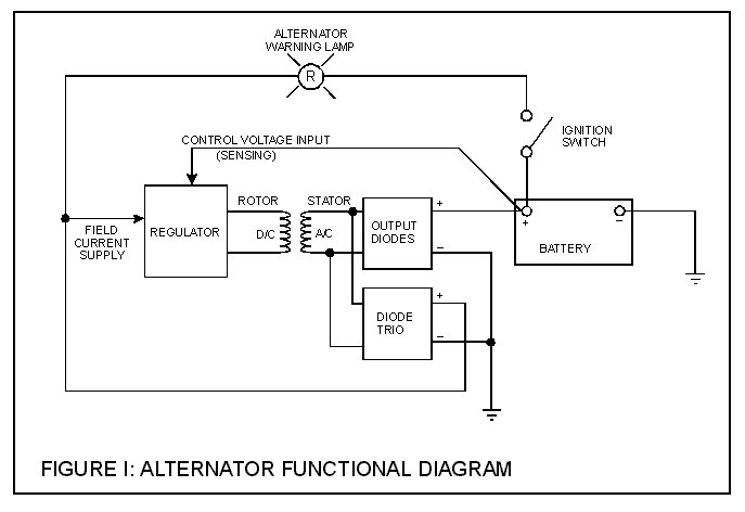
That's all well and good, but just exactly what does all that mean? To get a good idea, it is first necessary to understand how an alternator works. You don't need an engineering degree, just a basic understanding of the general principles. Figure 1, below, is a block diagram, or a "functional" diagram, of an alternator, and its connections to the remainder of the automobile electrical system. Following the figure is a description of the various components that make up an alternator, and a description of how each operates to keep the battery charged in your car.

Figure 1: alternator functional diagram

ALTERNATOR ROTOR

We'll start our tour of the alternator where it all starts in the alternator itself - at the alternator rotor. The rotor consists of a coil of wire wrapped around an iron core. Current through the wire coil - called "field" current - produces a magnetic field around the core. The strength of the field current determines the strength of the magnetic field. The field current is D/C, or direct current. In other words, the current flows in one direction only, and is supplied to the wire coil by a set of brushes and slip rings. The magnetic field produced has, as any magnet, a north and a south pole. The rotor is driven by the alternator pulley, rotating as the engine runs, hence the name "rotor."

STATOR

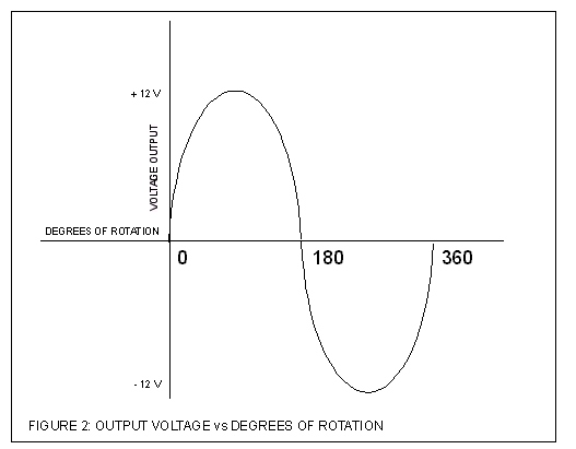
Surrounding the rotor is another set of coils, three in number, called the stator. The stator is fixed to the shell of the alternator, and does not turn. As the rotor turns within the stator windings, the magnetic field of the rotor sweeps through the stator windings, producing an electrical current in the windings. Because of the rotation of the rotor, an alternating current is produced. As, for example, the north pole of the magnetic field approaches one of the stator windings, there is little coupling taking place, and a weak current is produced, As the rotation continues, the magnetic field moves to the center of the winding, where maximum coupling takes place, and the induced current is at its peak. As the rotation continues to the point that the magnetic field is leaving the stator winding, the induced current is small. By this time, the south pole is approaching the winding, producing a weak current in the opposite direction. As this continues, the current produced in each winding plotted against the angle of rotation of the rotor has the form shown in figure 2. The three stator windings are spaced inside the alternator 120 degrees apart, producing three separate sets, or "phases," of output voltages, spaced 120 degrees apart, as shown in figure 3.

Figure 2: output voltage vs degrees of rotation - single phase Figure 3: output voltage vs degrees of
rotation - 3 phase

OUTPUT DIODES

A/C voltage is of little use in a D/C system, such as used in an automobile, so it has to be converted to D/C before it can be used. This conversion to D/C takes place in the "output diodes" and in the "diode trio." Diodes have the property of allowing current to flow in only one direction, while blocking current flow in the other direction. The output diodes consist of six diodes, one pair for each winding. One of the pair is for the negative half cycle, and the other for the positive half cycle. As a result of this diode rectification, the output of the alternator looks as shown in figure 4.

Figure 4: pulsed DC voltage

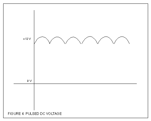
Surprisingly enough, the output of the alternator is not a pure D/C as one might expect, but a pulsating D/C. Because there are three windings, each with a positive and a negative half, by the time the voltage is passed through the diodes, there are six pulsations for each rotation of the rotor. This is close enough to D/C for most automotive components. Critical components, such as radios, have their own internal filtering circuits to further smooth out the waveform to a purer D/C.

DIODE TRIO

The diode trio consists, as the name suggests, of three diodes, one per phase, which provides field current to the alternator regulator. This output will be discussed in more detail later in the "field current supply" section.

REGULATOR

The regulator has two inputs and one output. The inputs are the field current supply and the control voltage input, and the output is the field current to the rotor. The regulator uses the control voltage input to control the amount of field current input that is allow to pass through to the rotor winding. If the battery voltage drops, the regulator senses this, by means of the connection to the battery, and allows more of the field current input to reach the rotor, which increases the magnetic field strength, which ultimately increases the voltage output of the alternator. Conversely, if the battery voltage goes up, less field current goes through the rotor windings, and the output voltage is reduced.

FIELD CURRENT SUPPLY

Field current supply is provided from two different sources - from the alternator itself, via the diode trio, and from the battery, via the alternator warning lamp. When you first get in the car and turn the key on, the engine is not running and the alternator is not spinning. At this time, the voltage/current source for the field current is from the battery, through the ignition switch, and through the warning lamp. After the engine is started, and the alternator is up to speed, the output of the diode trio is fed back to the regulator, and serves as a source of current for the field current. At this time, the alternator is self sustaining, and the battery is no longer needed to power the automobiles electrical system WARNING!!! This is theoretical only - in actual practice, the voltage surges resulting from disconnecting the battery can seriously damage the regulator circuitry. All alternator manufacturers strongly advise NOT doing this! This test will not prove the functionality of the alternator anyway, as the engine may still run with a weak alternator output.

WARNING LAMP

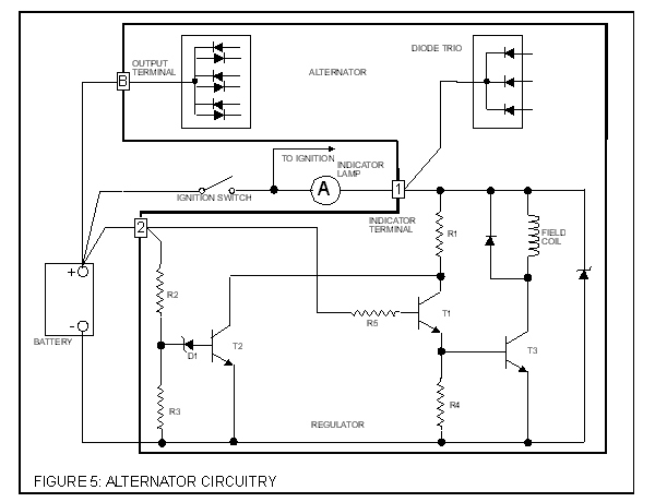
This brings us back full circle to the starting point - the alternator warning lamp. As can be seen from figure 5, a schematic for an actual alternator, there is a path to ground from the field current supply input [1] to the regulator. As a result, when the key is turned on, current flows through the warning lamp, through the resisters, transistors, and field coil, and then to ground, causing the lamp to illuminate. Once the alternator is at full output, voltage from the diode trio, also applied to [1], equals the battery voltage. At this time, with 12 volts on both sides, the lamp is out.

Figure 5: Alternator Circuitry

If the alternator should fail, voltage from the diode trio would drop, and once again the lamp would light from the battery voltage. If the alternator output is only a little low, the lamp will be dimly lit. If the alternator fails completely, and the output voltage goes to zero, the lamp will be lit at full brilliance. Conversely, if the battery should fail, and the battery voltage drops, with the output voltage of the alternator on one side and the low battery voltage on the other, the lamp will also light.

As stated earlier, if the light grows dimmer as the engine is revved up, it is because the alternator voltage is rising with the RPM, producing more voltage on the alternator side of the lamp. The closer the output voltage gets to the battery voltage, the dimmer the bulb becomes. By the same way, if the light gets brighter with increasing RPM, it is because as the alternator voltage increases, it is getting higher than the battery voltage. The higher the voltage with respect to the battery voltage, the greater the voltage difference across the lamp, and the brighter it gets.

SUMMATION

In summary, then, we can say that field current through the rotor coils produces a magnetic field, which is coupled over to the stator coils, producing an AC voltage. This AC voltage is converted by the output diodes into pulsating DC voltage, which charges the battery.

The field current is supplied from either the battery, via the warning lamp, or from the diode trio. The amount of field current allowed to pass through the regulator to the rotor, or field coil, is controlled by the voltage feedback from the battery.

And there you have it - the complete operation of an alternator in a nutshell. The next time you see the little red light, you will know exactly what it is trying to tell you.

Thursday, March 12, 2009

Heating System (Cooling system 11)

You may have heard the advice that if you car is overheating, open all the windows and run the heater with the fan going at full blast. This is because the heating system is actually a secondary cooling system that mirrors the main cooling system on your car.

undefined
Heater plumbing

The heater core, which is located in the dashboard of your car, is really a small radiator. The heater fan blows air through the heater core and into the passenger compartment of your car.

undefined
A heater core looks like a small radiator.

The heater core draws its hot coolant from the cylinder head and returns it to the pump -- so the heater works regardless of whether the thermostat is open or closed.

For more information on car cooling systems and related topics, check out the links on the next page.

Wednesday, March 11, 2009

Fan (Cooling system 10)

Like the thermostat, the cooling fan has to be controlled so that it allows the engine to maintain a constant temperature.

Front-wheel drive cars have electric fans because the engine is usually mounted transversely, meaning the output of the engine points toward the side of the car. The fans are controlled either with a thermostatic switch or by the engine computer, and they turn on when the temperature of the coolant goes above a set point. They turn back off when the temperature drops below that point.

undefined
Cooling fan

Rear-wheel drive cars with longitudinal engines usually have engine-driven cooling fans. These fans have a thermostatically controlled viscous clutch. This clutch is positioned at the hub of the fan, in the airflow coming through the radiator. This special viscous clutch is much like the viscous couplingsometimes found in all-wheel drive cars.

Saturday, March 7, 2009

Thermostat (Cooling system 9)

The thermostat's main job is to allow the engine to heat up quickly, and then to keep the engine at a constant temperature. It does this by regulating the amount of water that goes through the radiator. At low temperatures, the outlet to the radiator is completely blocked -- all of the coolant is recirculated back through the engine.

Once the temperature of the coolant rises to between 180 and 195 F (82 - 91 C), the thermostat starts to open, allowing fluid to flow through the radiator. By the time the coolant reaches 200 to 218 F (93 - 103 C), the thermostat is open all the way.


The open and closed positions of a thermostat

If you ever have the chance to test one, a thermostat is an amazing thing to watch because what it does seems impossible. You can put one in a pot of boiling water on the stove. As it heats up, its valve opens about an inch, apparently by magic! If you'd like to try this yourself, go to a car parts store and buy one for a couple of bucks.

The secret of the thermostat lies in the small cylinder located on the engine-side of the device. This cylinder is filled with a wax that begins to melt at around 180 F (different thermostats open at different temperatures, but 180 F is a common one). A rod connected to the valve presses into this wax. When the wax melts, it expands significantly, pushing the rod out of the cylinder and opening the valve. If you have read How Thermometers Work and done the experiment with the bottle and the straw, you have seen this process in action -- the wax just expands a good bit more because it is changing from a solid to a liquid in addition to expanding from the heat.

This same technique is used in automatic openers for greenhouse vents and skylights. In these devices, the wax melts at a lower temperature.

Friday, March 6, 2009

Pressure Cap (Cooling system 8)

The radiator cap actually increases the boiling point of your coolant by about 45 F (25 C). How does this simple cap do this? The same way a pressure cooker increases the boiling temperature of water.

The cap is actually a pressure release valve, and on cars it is usually set to 15 psi. The boiling point of water increases when the water is placed under pressure.

When the fluid in the cooling system heats up, it expands, causing the pressure to build up. The cap is the only place where this pressure can escape, so the setting of the spring on the cap determines the maximum pressure in the cooling system. When the pressure reaches 15 psi, the pressure pushes the valve open, allowing coolant to escape from the cooling system. This coolant flows through the overflow tube into the bottom of the overflow tank. This arrangement keeps air out of the system. When the radiator cools back down, a vacuum is created in the cooling system that pulls open another spring loaded valve, sucking water back in from the bottom of the overflow tank to replace the water that was expelled.

Radiator (Cooling system 7)

A radiator is a type of heat exchanger. It is designed to transfer heat from the hot coolant that flows through it to the air blown through it by the fan.

Most modern cars use aluminum radiators. These radiators are made by brazing thin aluminum fins to flattened aluminum tubes. The coolant flows from the inlet to the outlet through many tubes mounted in a parallel arrangement. The fins conduct the heat from the tubes and transfer it to the air flowing through the radiator.

The tubes sometimes have a type of fin inserted into them called a turbulator, which increases the turbulence of the fluid flowing through the tubes. If the fluid flowed very smoothly through the tubes, only the fluid actually touching the tubes would be cooled directly. The amount of heat transferred to the tubes from the fluid running through them depends on the difference in temperature between the tube and the fluid touching it. So if the fluid that is in contact with the tube cools down quickly, less heat will be transferred. By creating turbulence inside the tube, all of the fluid mixes together, keeping the temperature of the fluid touching the tubes up so that more heat can be extracted, and all of the fluid inside the tube is used effectively.

cooling-system-tank

Radiators usually have a tank on each side, and inside the tank is a transmission cooler. In the picture above, you can see the inlet and outlet where the oil from the transmission enters the cooler. The transmission cooler is like a radiator within a radiator, except instead of exchanging heat with the air, the oil exchanges heat with the coolant in the radiator.

source http://auto.howstuffworks.com

Thursday, March 5, 2009

Engine (Cooling system 6)

The engine block and cylinder head have many passageways cast or mach ined in them to allow for fluid flow. These passageways direct the coolant to the most critical areas of the engine.

cooling-system-engine

Temperatures in the combustion chamber of the engine can reach 4,500 F (2,500 C), so cooling the area around the cylinders is critical. Areas around the exhaust valves are especially crucial, and almost all of the space inside the cylinder head around the valves that is not needed for structure is filled with coolant. If the engine goes without cooling for very long, it can seize. When this happens, the metal has actually gotten hot enough for the piston to weld itself to the cylinder. This usually means the complete destruction of the engine.

cooling-system-head

One interesting way to reduce the demands on the cooling system is to reduce the amount of heat that is transferred from the combustion chamber to the metal parts of the engine. Some engines do this by coating the inside of the top of the cylinder head with a thin layer of ceramic. Ceramic is a poor conductor of heat, so less heat is conducted through to the metal and more passes out of the exhaust.


source: http://auto.howstuffworks.com

Wednesday, March 4, 2009

Water pump (cooling system 5)

A water pump is an important part of the engine cooling system. It provides circulation of the engine coolant (antifreeze) through the cooling system (see the top picture).

A water pump pushes the coolant through the passages (water jackets) in the engine cylinder block and cylinder head and then out into the radiator. This helps to keep the engine from overheating; the hot coolant passes through the radiator where it cools down and then returns back to the engine.

A water pump is usually driven by the engine through the drive belt. Sometimes it's driven by a timing belt. A water pump consists of the housing with the shaft rotating on the bearing pressed inside.

At the outer side there is a pulley mounted on the shaft. At the inner side there is a seal to keep the coolant from leaking out and the impeller that acts like a centrifugal pump (see the lower picture).

water_pump2

Monday, March 2, 2009

Fluid (Cooling System 4)

Cars operate in a wide variety of temperatures, from well below freezing to we ll over 100 F (38 C). So whatever fluid is used to cool the engine has to have a very low freezing point, a high boiling point, and it has to have the capacity to hold a lot of heat.

Water is one of the most effective fluids for holding heat, but water freezes at too high a temperature to be used in car engines. The fluid that most cars use is a mixture of water and ethylene glycol (C2H6O2), also known as antifreeze. By adding ethylene glycol to water, the boiling and freezing points are improved significantly.


Pure Water

50/50
C2H6O2/Water

70/30
C2H6O2/Water

Freezing Point

0 C / 32 F

-37 C / -35 F

-55 C / -67 F

Boiling Point

100 C / 212 F

106 C / 223 F

113 C / 235 F

The temperature of the coolant can sometimes reach 250 to 275 F (121 to 135 C). Even with ethylene glycol added, these temperatures would boil the coolant, so something additional must be done to raise its boiling point.

The cooling system uses pressure to further raise the boiling point of the coolant. Just as the boiling temperature of water is higher in a pressure cooker, the boiling temperature of coolant is higher if you pressurize the system. Most cars have a pressure limit of 14 to 15 pounds per square inch (psi), which raises the boiling point another 45 F (25 C) so the coolant can withstand the high temperatures.

Antifreeze also contains additives to resist corrosion.

source: http://www.howstuffworks.com

Sunday, March 1, 2009

Plumbing (Cooling System 3)

The cooling system in your car has a lot of plumbing. We'll start at the pump and work our way through the system, and in the next sections we'll talk about each part of the system in more detail.

The pump sends the fluid into the engine block, where it makes its way through passages in the engine around the cylinders. Then it returns through the cylinder head of the engine. The thermostat is located where the fluid leaves the engine. The plumbing around the thermostat sends the fluid back to the pump directly if the thermostat is closed. If it is open, the fluid goes through the radiator first and then back to the pump.

There is also a separate circuit for the heating system. This circuit takes fluid from the cylinder head and passes it through a heater core and then back to the pump.

On cars with automatic transmissions, there is normally also a separate circuit for cooling the transmission fluid built into the radiator. The oil from the transmission is pumped by the transmission through a second heat exchanger inside the radiator.

source: http://auto.howstuffworks.com